The circuit diagram of Hartley Oscillator is as shown in figure below. It uses two inductors placed across common capacitor C and the center of two inductors ins tapped. The tank circuit is made up of L1 , L2 and C and is given by.
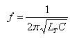
where LT = L1 + L2 + 2M
M= Mutual inductance between L1 and L2

- When the circuit is turned ON, the capacitor is charged. When this capacitor is fully charged, it discharges through coils L1 and L2 setting up oscillations of frequency determined by expression 1. The output voltage of the amplifier appears across L2 and feedback voltage across L1. The voltage across L1 is 1800 out of phase with the voltage developed across L2.
- A phase shift of 1800 is produced by the transistor and a further phase shift of 1800 is produced by L1-L2 voltage divider circuit. In this way feedback is properly phased to produce continuous undamped oscillations.
Feedback fraction- In Hartley oscillator the feedback voltage is across L1 and output voltage is across L2.

Aucun commentaire:
Enregistrer un commentaire